-
Valve Categories
-


-
Valve Categories
-
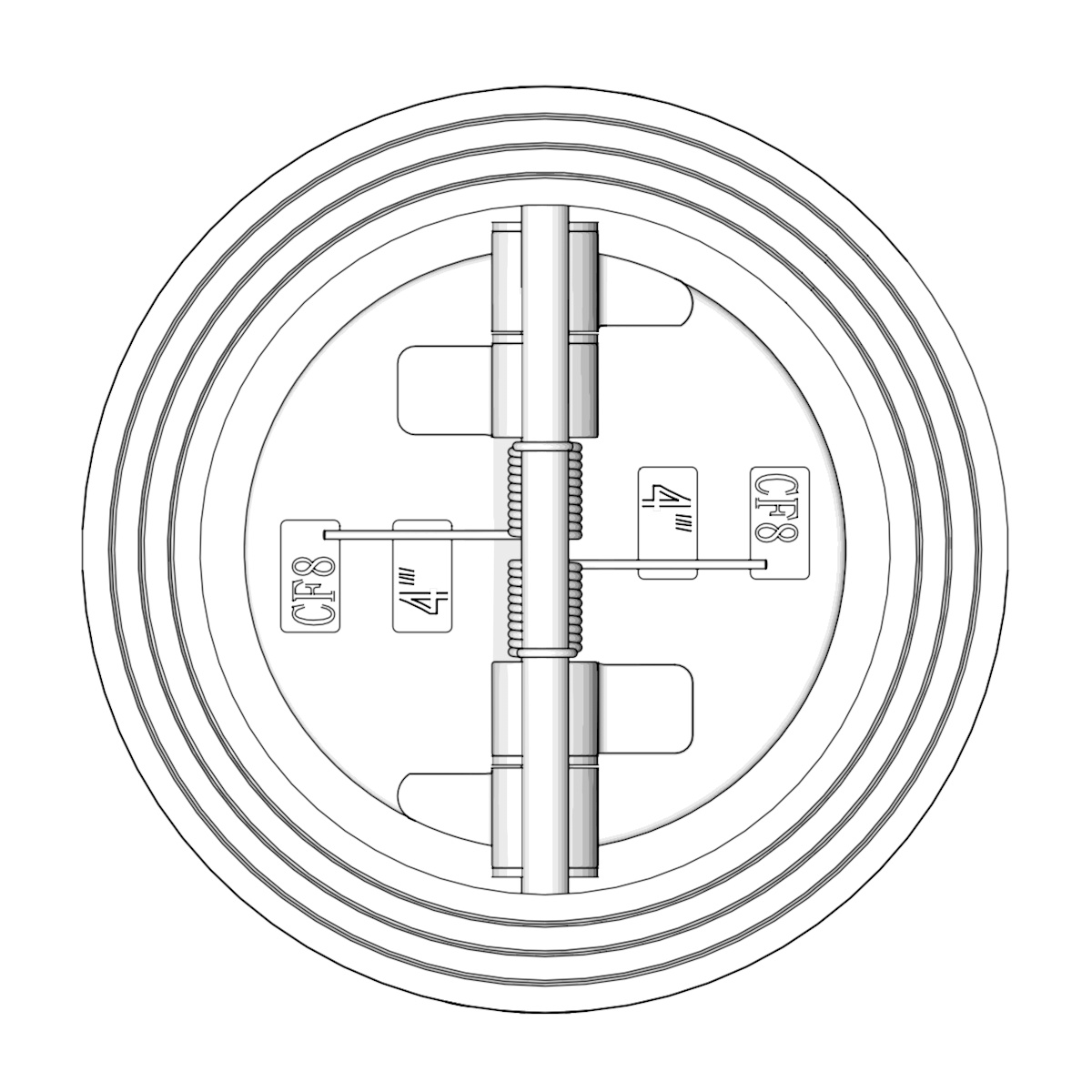
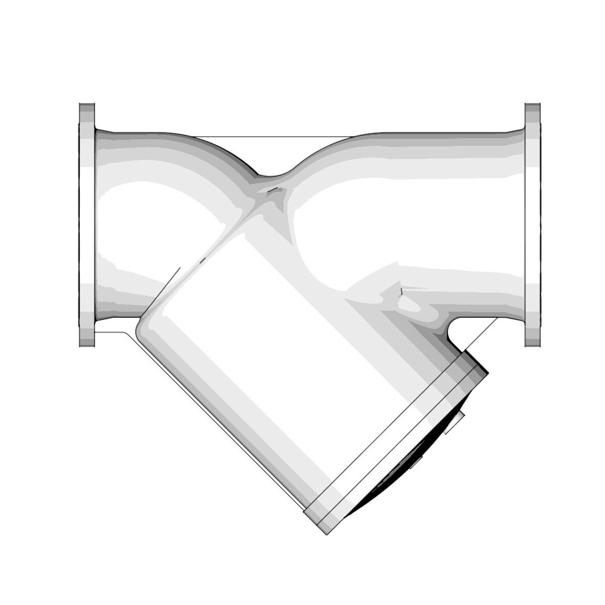
Flanged Y-shaped Filter SF41
DN
15~600 (1/2"~24")
PN
10~25 (Class150)
Temperature Range
-59°C~450°C
Connection
Flanged, Threaded
Installation Direction
Unidirectional
Design
HG/T21637
Face to Face
DIN3202 F6, GB/T12221, EN558-1
Flange Drilling
GB/T9113, ASME B16.5, EN1092, GOST12820, GOST33259
Thread
GB/T192, GB/T193, NPT, BSP
Inspection
GB/T13927, ISO5028, API598, JB/T9092
Body Materials
GGG40, WCB, CF8, CF8M
Screen Materials
304, 316, 304L, 316L
Fastener Materials
201, 304, 316
Gasket Materials
EPDM, NBR, PTFE, Graphite

Features & Benefits
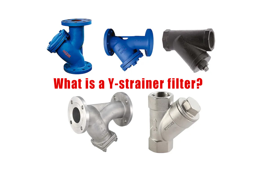
SF41 is an indispensable filtering device in pipeline systems for conveying media. It is usually installed at the inlet end of pressure reducing valves, relief valves, constant water level valves, or other equipment to remove impurities from the medium and protect the normal use of valves and equipment. The Y-shaped filter has the characteristics of advanced structure, low resistance, and convenient discharge.
Industry Options
| Materials | Cr | Ni | Mo | Ti | Temp. Range ℃ |
| WCB | 0.5 | 0.5 | 0.2 | - | -29~425 |
| WCC | 0.5 | 0.5 | 0.2 | - | -29~425 |
| WC1 | 0.35 | 0.5 | 0.45~0.65 | - | ≤455 |
| WC5 | 0.5~0.9 | 0.6~1 | 0.9~1.2 | - | ≤565 |
| WC6 | 1~1.5 | - | 0.45~0.65 | - | ≤595 |
| WC9 | 2~2.75 | - | 0.9~1.2 | - | ≤595 |
| C5 | 4~6.5 | - | 0.45~0.65 | - | ≤650 |
| CF8 | 18~21 | 8~11 | 0.05 | - | ≤458 (540) |
| CF8M | 18~21 | 9~13 | 2~3 | - | ≤425 (540) |
| CF3 | 17~21 | 8~12 | 0.5 | - | ≤425 |
| CF3M | 17~21 | 9~13 | 2~3 | - | ≤455 |
| 321 | 17~19 | 9~12 | - | 0.5 | ≤540 (700) |
| 904L | 19~21 | 24~26 | - | - | -165~600 |
| 316Ti | 16~18 | 10~14 | - | 0.7 | -165~600 |
| 310S | 24~26 | 19~22 | - | - | ≤850 |
| LCB | - | - | - | - | -46~345 |
| LCC | - | - | - | - | -46~345 |
| LC1 | - | - | - | - | -59~345 |
Dimensions

EN1092-2
| DN | L | D | D1 | D2 | b | f | n-Φd |
| 15 | 130 | 95 | 65 | 45 | 14 | 2 | 4-14 |
| 20 | 150 | 105 | 75 | 55 | 14 | 2 | 4-14 |
| 25 | 160 | 115 | 85 | 68 | 14 | 2 | 4-14 |
| 32 | 180 | 140 | 100 | 78 | 16 | 2 | 4-18 |
| 40 | 200 | 150 | 110 | 88 | 16 | 3 | 4-18 |
| 50 | 230 | 165 | 125 | 102 | 16 | 3 | 4-18 |
| 65 | 290 | 185 | 145 | 120 | 18 | 3 | 8-18 |
| 80 | 310 | 200 | 160 | 135 | 20 | 3 | 8-18 |
| 100 | 350 | 220 | 180 | 155 | 20 | 3 | 8-18 |
| 125 | 400 | 250 | 210 | 185 | 22 | 3 | 8-18 |
| 150 | 480 | 285 | 240 | 210 | 24 | 3 | 8-22 |
| 200 | 600 | 340 | 295 | 265 | 26 | 3 | 12-22 |
| 250 | 730 | 405 | 355 | 320 | 30 | 3 | 12-26 |
| 300 | 850 | 460 | 410 | 375 | 30 | 4 | 12-26 |
| 350 | 980 | 520 | 470 | 435 | 34 | 4 | 16-26 |
| 400 | 1100 | 580 | 525 | 485 | 36 | 4 | 16-30 |
| 450 | 1200 | 640 | 585 | 545 | 40 | 4 | 20-30 |
| 500 | 1250 | 715 | 650 | 608 | 44 | 4 | 20-33 |
| 600 | 1450 | 840 | 770 | 718 | 48 | 5 | 20-36 |
RELATED CASE

Submit An inquiry

© 2024 Seallon Flow Technology Co.,Ltd. All Rights Reserved