Research: Common Valve Symbols and Main Functions in Piping and Instrumentation Diagrams (P&IDs)
When working with process control systems, understanding valve symbols is essential for reading P&ID drawings and designing industrial piping systems. Whether you're in oil & gas, HVAC, chemical processing, or water treatment, knowing how to interpret common valve symbols and their main functions helps ensure safe and efficient system design.
This guide breaks down the most frequently used valve types, their symbols, and key industrial applications — using high-traffic search keywords for maximum discoverability.
🔧 What Are Valve Symbols?
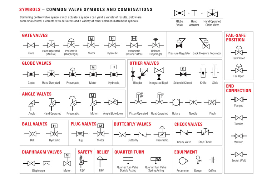
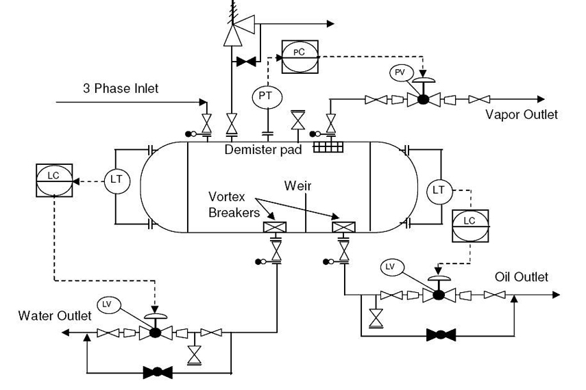
Valve symbols are standardized graphical representations used in P&ID (Piping and Instrumentation Diagrams) and engineering schematics to show the type, function, and control method of valves within a process system.
These symbols follow ISA (Instrumentation Society of America) or ISO 14617 standards and help engineers and operators quickly identify valve configurations during design, operation, and troubleshooting.
🧭 Main Valve Functions in Industrial Systems
Valves serve multiple roles depending on process requirements:
| Function | Valve Type Examples | Typical Applications |
|---|---|---|
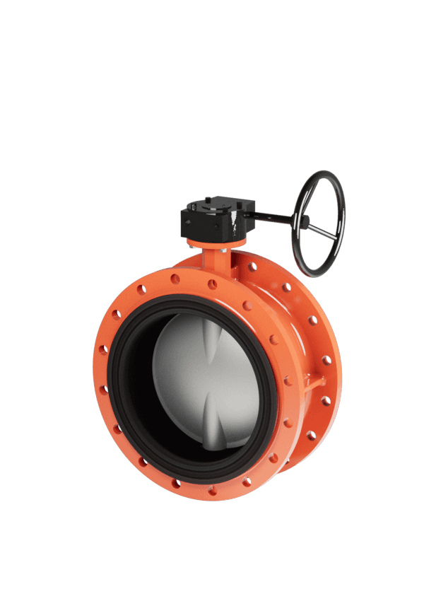
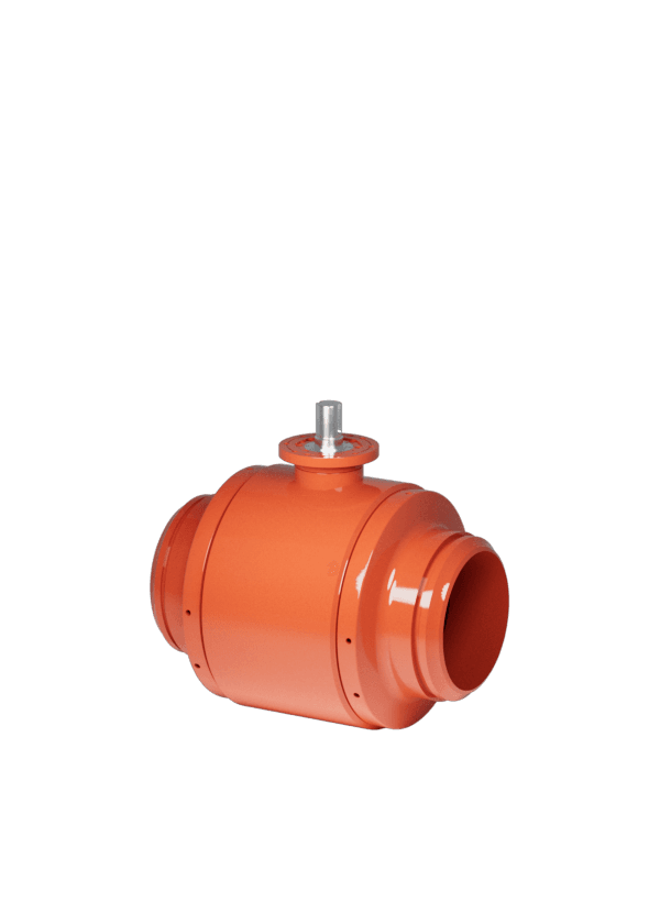
| Isolation | Gate valve, Ball valve, Butterfly valve | Shutdown, line maintenance |
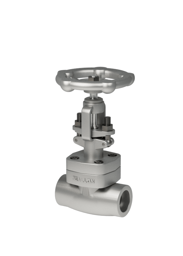
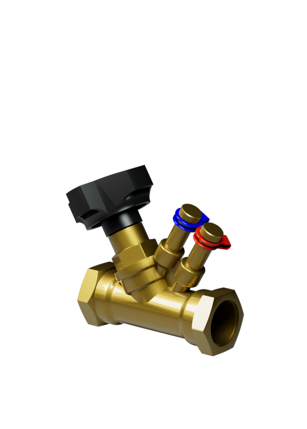
| Throttling | Globe valve, Needle valve, Butterfly valve | Flow regulation, pressure reduction |
| Backflow Prevention | Check valve, Non-return valve (NRV) | Pump discharge, pipeline safety |
| Pressure Control | Pressure reducing valve, Relief valve | Boiler systems, compressors |
| Flow Direction Control | 3-way and 4-way directional valves | Hydraulic and pneumatic circuits |
| Emergency Shutdown | Solenoid valve, Quick-closing valves | Fire safety, toxic gas systems |
| Automated Control | Control valve with actuator + positioner (e.g. globe, ball) | Process control loops (flow, temp, pressure, level) |
⚙️ Symbol Additions for Actuation and Control
P&ID valve symbols often include modifiers that indicate the method of actuation:
| Actuation Method | Symbol Add-on | Description |
|---|---|---|
| Manual (handwheel) | ▓ or a solid line | Operator opens/closes valve manually |
| Pneumatic actuator | (P) | Valve actuated with compressed air |
| Electric actuator | (E) | Valve motorized via electric signal |
| Hydraulic actuator | (H) | Valve controlled by hydraulic pressure |
| Solenoid control | [S] | Electromagnetically operated |
| Smart positioner | (IP), (HART) | Enables remote or feedback control |
🌍 Why Understanding Valve Symbols Matters
✅ Improves communication between engineers, operators, and maintenance teams
✅ Prevents misinterpretation during installation, commissioning, or troubleshooting
✅ Enhances safety in critical systems like boilers, refineries, and chemical plants
Whether you're selecting an on/off isolation valve, a flow control butterfly valve, or a pressure relief valve, knowing the correct symbol ensures smoother project delivery.
🏷️ Seallon Tip: Streamline Design with Clear Valve Identification
If you’re working with Seallon industrial valves, such as the SB71 series butterfly valve, our engineering documentation includes:
-
Full P&ID symbols in DWG/PDF format
-
Valve data sheets with Cv values, pressure ratings, and actuator options
-
Support for integration with HART-compatible smart positioners
-
Custom valve tag templates and selection charts