-
Valve Categories
-


-
Valve Categories
-
Flanged Flexible Rubber Joint SR41
DN
15~3000 (1/2"~120")
PN
1.0~4.0 (Class150~300)
Temperature Range
-20°C~130°C
Connection
Flanged, Threaded
Installation Direction
Bidirectional
Design
CJ/T 208, HG/T2289
Face to Face
GB/T12221, EN558-1
Flange Drilling
GB/T9113, ASME B16.5, EN1092, GOST12820, GOST33259
Thread
GB/T192, GB/T193, NPT, BSP
Inspection
GB/T13927, ISO5028, API598, JB/T9092
Flange Materials
Q235, 304, 316, 321
Rubber Materials
EPDM, NBR, PTFE, Viton
Pull Rods Materials
201, 304, 316
Coating Materials
Epoxy spray coating, Galvanized

Features & Benefits
SR41 is a flexible rubber joint, abbreviated as rubber joint, is a joint composed of fabric reinforced rubber parts, flat flexible joints, metal flanges or threaded pipe flanges, used for pipeline vibration isolation, noise reduction and displacement compensation. It is a pipeline joint with high elasticity, high airtightness, medium resistance, and weather resistance.
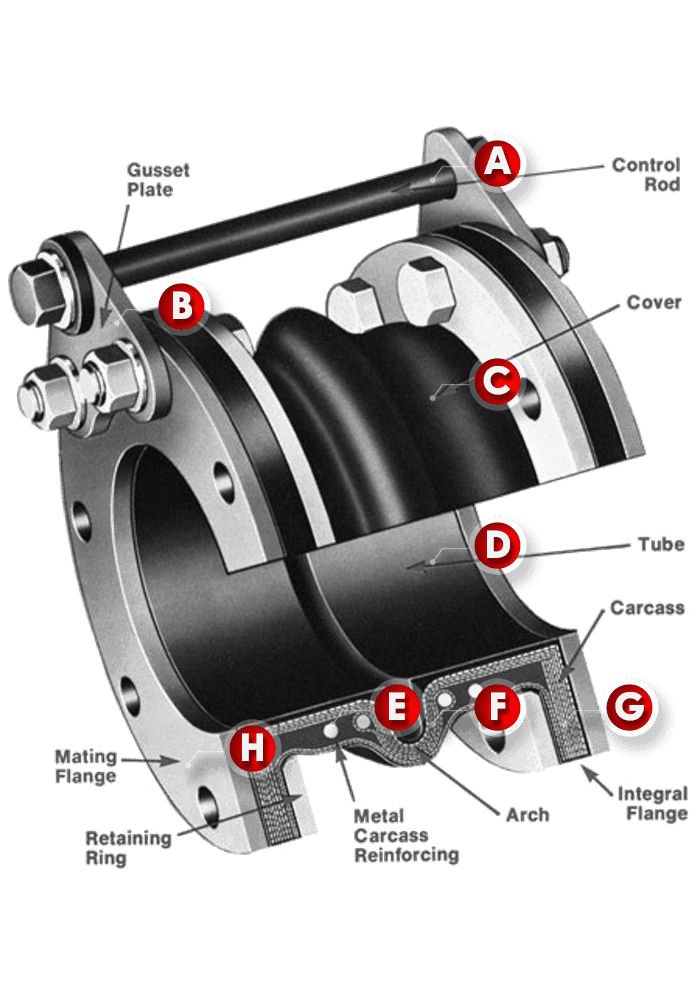
Prevents excessive movement of the joint caused by thermal expansion, pressure thrust, or other forces. It protects the joint from overextension or compression.
Provides additional structural support to maintain alignment and stability under pressure or load.
The outermost layer of the rubber joint that protects the inner layers from external environmental factors like ozone, weathering, and mechanical damage.
The innermost layer of the joint, designed to resist chemical corrosion and abrasion caused by the conveyed fluid.
Holds the flanges in place, ensuring proper sealing and mechanical stability.
Increases the flexibility of the joint, allowing it to absorb vibrations, thermal expansion, and contraction.
Reinforced fabric layers that provide the joint with the necessary strength to withstand internal pressure and mechanical forces.
The flange on the connected piping that aligns with the integral flange of the expansion joint to form a secure connection. It can be customized by different standards or special request.
Industry Options
| Materials | Characteristics | Low Temp. ℃ | High Temp. ℃ | Recommended ℃ |
| NR | High elasticity | -20 | 85 | -5~70 |
| NBR | Oil resistivity | -30 | 100 | -15~90 |
| EPDM | Aging resistance, ozone resistance, corrosion resistance | -40 | 125 | -25~110 |
| HT EPDM | Aging resistance, ozone resistance, corrosion resistance, heat resistance | -40 | 150 | -25~135 |
| Wear-resistant | Excellent traction performance and wear resistance | -30 | 100 | -15~100 |
| CR | Oil, heat, flame, sunlight, ozone, acid and alkali resistance | -30 | 125 | -15~100 |
| Hypalon | Oxidation resistance, resistance to winding and cracking | -40 | 120 | -25~110 |
| FPM (Viton) | Chemical and most oils resistance, (except ketones & esters) | -20 | 200 | -5~150 |
| MVQ (Silicon) | High and low temperature resistance, oil, corrosion resistance | -55 | 200 | -30~180 |
| PTFE | Heat, cold, acid, alkali, organic solvents resistant | -60 | 180 | -45~150 |
Dimensions
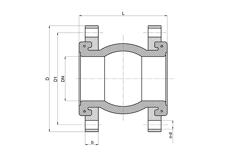
GB/T 9113 PN16
| DN | L | D | D1 | D2 | b | f | n-Φd |
| 50 | 105 | 165 | 125 | 102 | 16 | 3 | 4-18 |
| 65 | 115 | 185 | 145 | 122 | 18 | 3 | 8-18 |
| 80 | 135 | 200 | 160 | 138 | 20 | 3 | 8-18 |
| 100 | 150 | 220 | 180 | 158 | 20 | 3 | 8-18 |
| 125 | 165 | 250 | 210 | 188 | 22 | 3 | 8-18 |
| 150 | 180 | 285 | 240 | 212 | 24 | 3 | 8-22 |
| 200 | 210 | 340 | 295 | 268 | 26 | 3 | 12-22 |
| 250 | 230 | 405 | 355 | 320 | 30 | 3 | 12-26 |
| 300 | 245 | 460 | 410 | 378 | 30 | 4 | 12-26 |
| 350 | 255 | 520 | 470 | 438 | 34 | 4 | 16-26 |
| 400 | 255 | 580 | 525 | 490 | 36 | 4 | 16-30 |
| 450 | 255 | 640 | 585 | 550 | 40 | 4 | 20-30 |
| 500 | 255 | 715 | 650 | 610 | 44 | 4 | 20-33 |
| 600 | 260 | 840 | 770 | 725 | 48 | 5 | 20-36 |
Download
View 3D models → www.seallon.com → Product Pages → Closer Look
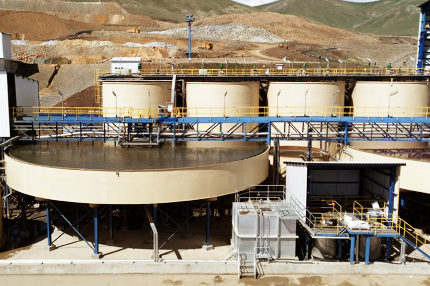
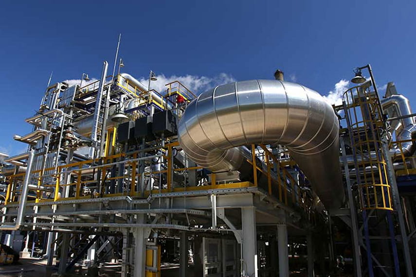
RELATED CASE

Submit An inquiry

© 2024 Seallon Flow Technology Co.,Ltd. All Rights Reserved